Friday, December 2, 2016

11/28: Physical Pendulum

Title: Physical Pendulum
Purpose: Derive expressions for the period of various physical pendulums and verify predicted periods by experiment.
Apparatus:

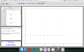
By hanging the ring as well as the triangle on a stand and then placing a photogate near where the rotation is, we can measure the period of oscillation. 

Theory
Parallel axis theorem is used to find the moment of inertia about the pivot point. With the new inertia, it can be used to find the angular acceleration. By the small angle estimation, we can find angular frequency, which is then used in an inverse relationship with period. 

Data: 


Calculation/Graphs
Period of Ring

Period of Triangle

Period of Upside Down Triangle

Calculation of Theoretical Period of Ring

Calculation of Theoretical Period of Triangle


Analysis
The point of pivot of the ring is assumed to be exactly half way between inner and outer radii and it has no impact on the uniformity of the mass distribution. The periods of the oscillating objects tended to decrease due to gravity, which is why the average of the periods is used instead. These pendulums cannot use the same model as a simple pendulum due to the differences in moments of inertia, which can impact everything. The mass of the pivot is negligible because it is very small in comparison to the whole object. 

Conclusion
The errors were all calculated to be less than 1%, showing that the model of parallel axis theorem as well as the small angle estimation are valid. Sources of error may be in the rotating pivot point, as there might be friction or other unaccounted forces. 


11/23: Mass-Spring Oscillations

Title: Mass-Spring Oscillation
Purpose: The purpose of this lab is to find the relationship between period, mass, and spring constant.
Apparatus: We attached a spring with a known mass to a stand and attached various weights to the spring. The spring and the hook both have a mass, so they must be accounted for. 1/3 of the spring's mass as well as the mass of the hook must be added in addition to the hanging mass to make for the total mass.

Theory:

With this relationship, the period can be determined as long as the spring constant is constant and mass is varying.

Data:
The different periods of varying spring constants with mass constant

The different periods of varying masses with spring constant constant

Graphs/Calculations:
Calculation of spring constant

Calculation of hanging mass

Calculation of theoretical period (1 example)

Graph of Period vs Mass

Graph of Period vs Spring Constant

Analysis:
To determine the spring constant, we measured the initial position of the spring. We attached a mass to the spring, and then determined how far the spring was stretched. The relationship F=kx was used to determine the spring constant. In order for the mass to be correct, 1/3 of the mass of the spring as well as the mass of the hook had to be taken into account. The graphs show a very nice power fit curve. The period vs mass was slightly more accurate to the fit than the period vs spring constant. However, both correlations are very close to 1. When the mass increased, the period increased. This is because the heavier weight on the spring causes it to spring back slower. The heavier weight is harder to fight against the natural gravitational acceleration of the earth. When the spring constant increased, the period decreased. The "stiffness" of the spring causes it to have a shorter period.

Conclusion:
The percent error of all the trials are less than 1%, with the exception of the 115g, which was at a 1.2% error. This shows that the theoretical model is a valid equation for finding periods of oscillations. Sources of error may form from timing the oscillations, as the time at which we started and stopped the stopwatch as well as counting the oscillations may be off.

11/21: Conservation of Linear and Angular Momentum

Title: Conservation of Linear and Angular Momentum
Purpose: The purpose of this lab is to find the conservation of angular momentum about a point that is external to a rolling ball.
Apparatus:
This was the apparatus used to determine the horizontal velocity of the ball. 

This is used to find the the conservation of angular momentum about a point external to the ball. 

Theory
When rolling the ball off the ramp and onto the ground, measurements can be made, and kinematics can be used to find the horizontal velocity of the ball, which should be constant as there are no external forces acting on the ball horizontally. 
The inertia of the apparatus itself can be determined, using the methods of previous experiments.
The ball is then rolled down the ramp, starting the apparatus. The conservation of angular momentum equation can then be used to find the omega of the ball, which can also be measured experimentally. 

Data


Calculation/Graphs
The angular acceleration of the apparatus

Calculation of horizontal velocity of the ball

Calculation of the moment of inertia of the apparatus:

Calculation of the theoretical angular velocities:

Analysis
The radius at which the ball is caught shows that the smaller the radius, the smaller the angular velocity is. The horizontal velocity of the ball affects the initial rotational speed of the apparatus. When we assume the momentum is conserved, the distance at which the ball is caught actually plays a large role.

Conclusion: 
The answers we derived theoretically and arrived at experimentally were at a 6.7% and 8.8% error between the 7.6 cm distance and 4.2 cm distance, respectively. Both these errors are within 10%, which is acceptable. Sources of error may be from when the horizontal velocity of the ball is calculated, as we are assuming that it is constant throughout and there are no outside forces acting upon it, when in reality, there is air drag upon it. Error may also be at the apparatus, while measuring the angular velocity and acceleration, as friction plays a part.  

11/21: Conservation of Energy/Angular Momentum

Title: Conservation of Energy and Angular Momentum
Purpose: The purpose of this lab is to prove that energy and angular momentum are both conserved.
Apparatus:
When the stick is released from a horizontal position, it will collide with a blob of clay at the bottom of the swing. The meter stick and the clay will stick together and swing to a final height.

Theory:
This collision can be divided into three parts. The first part would be a conservation of energy, with the meter having some gravitational potential energy while it's horizontal and then some angular and linear kinetic energy right before it hits the clay. When the collision occurs, momentum is conserved. Immediately after, both the clay and meter stick together will rise to some height, and energy is conserved.

Data:
The point of maximum height

Masses

Calculations/Graph:
Theoretical height of the stick-clay system


Graph and Actual Height


Analysis:
Because we assume that energy and momentum is conserved, this calculation can be done. From the points on the x and y graphs, it can be seen that the points sort of follow a pattern and kind of match up to the appropriate places. Since it is an inelastic collision, the velocity after would certainly be less than the velocity before, and the slopes of the y prove just so.

Conclusion:
Our numbers match up quite well, being almost exactly the same. It is less than a 1% error. This proves that energy and momentum are both conserved. Places of uncertainty and error may be in video capture as well as calculation roundings.

11/16: Moment of Inertia of a Uniform Triangle

Title: Moment of Inertia of a Uniform Triangle
Purpose: The purpose of this lab is to determine the moment of inertia of a right triangular thin plate around its center of mass, for two perpendicular orientations of the triangle.
Theory:
Finding the moment of axis for a triangle is much easier around the axis at the edge than the center of mass, so finding the moment of inertia of a triangle around its center mass needs the parallel axis theorem.

Apparatus:

By using the disk rotation system, we can measure the angular acceleration of the system and use that to find the moment of inertia of the system. The moment of inertia of the triangle would be the difference in the moment of inertia of the system and with a triangle attached.

Data:


Calculations
Calculation for the theoretical moment of inertia around the center of mass of the two triangles

Calculation for the experimental moment of inertia around the center of mass

Analysis:

This is the derivation of how the moment of inertia for the center of mass is found theoretically.

Conclusions:
The results were all within 10%, which is a decent result. Where the most error may have occurred is the measurement of angular acceleration, as the apparatus was not entirely frictionless. Even though it is already accounted for in the calculation, it is still someplace error could have occurred. Another would be  the fact that the triangular plates still has some mass to it, even though we considered it to be negligible.


11/16: Moment of Inertia and Frictional Torque

Title: Moment of Inertia and Frictional Torque
Purpose: The purpose of this lab was to find the frictional torque of the apparatus and then use it to calculate and estimate how fast it would take for a cart to travel one meter.
Apparatus:

We measured the dimensions of the disk and the cylinders, and then used it to find the inertia of the system. Then, we spun the disk and used video capture to find the acceleration. With that and the inertia we found, we used it to find the frictional torque of the system. We attached the cart to the system, and let it travel down one meter and timed it. To estimate the time, we wrote equations from the rigid body diagram and then used kinematics to find the time.

Theory:
Inertia times angular acceleration should equal to the rotational torque minus the frictional torque. Since the only torque acting on the apparatus is the tension from the string, that is the only rotational torque at work. After finding the acceleration, we can plug that into a kinematics equation and find the time it takes for the cart to travel 1 meter.

Data:


Calculations
Calculation for moment of inertia of the apparatus

Calculation of the frictional torque

Analysis:
With all the dimensions we measured, we were able to calculate the volume. The total mass is known, but the masses of the individual parts are unknown. However, with the volume, we are able to calculate the total volume and the ratio of the volume as the whole. The mass should have the same ratio as the volume, so the individual masses could be found. With that, we could find the moments of inertia of each individual bit, and find the total inertia. That can be used to find the frictional torque, with the acceleration calculated from video capture of the spinning disk. With all of this, we found the theoretical time it would take for the cart to travel one meter while being attached to the apparatus. From the data we collected, it can be seen that the results were pretty close.

Conclusion:
The time we predicted was 10.45s, and the average of the times we measured was 10.38, with the percent error being only 0.67%, showing that the model works, and there is a frictional torque on the apparatus. The part where the most error might have occurred is during video capture to find the acceleration, where each dot may not have been at the exact correct place.